Hi, I’m Jorge Amengol, a fresh graduate student of the Game Development - Advanced Programming course at Fanshawe College, Canada. I started this series of posts to register my own progress throughout the program and also serve as a reference for me on important subjects in the future. Though it is a personal record, you might find the subjects discussed here useful. Feel free to make comments at the end of each post.
Introduction
When I was trying to implement the Collision Detection to my incipient game engine last week, I had some problems figuring out if the design was even right. I put some scratch in the paper and went directly to the code when I realized that I didn’t know if what I was thinking had a coherent logic. I figured out then that I needed to visualize it before anything else, so I started a series of visual aids to be able to tell if I was right or wrong before trying to implement the logic in the Physics engine.
Visualizing the Axis-aligned Bounding Boxes (AABBs)
The first thing I needed to make sure was working right was the AABBs. I have already written about them and how I implemented them here. Basically they are constructed to narrow your collision calculations. To print them at the screen, my first try was using the cDebugRender Class that Professor Feeney gave us in class. I got it working for the bounding boxes, printing lines for the sides of the cube and assembling all together to display them. It worked great for that job.
The way I created the AABBs was that it would be at least one AABB wherever there was a vertex, thus a triangle, and even more than one for triangle if the triangle was too big for it. I loaded a mesh and then got this result:
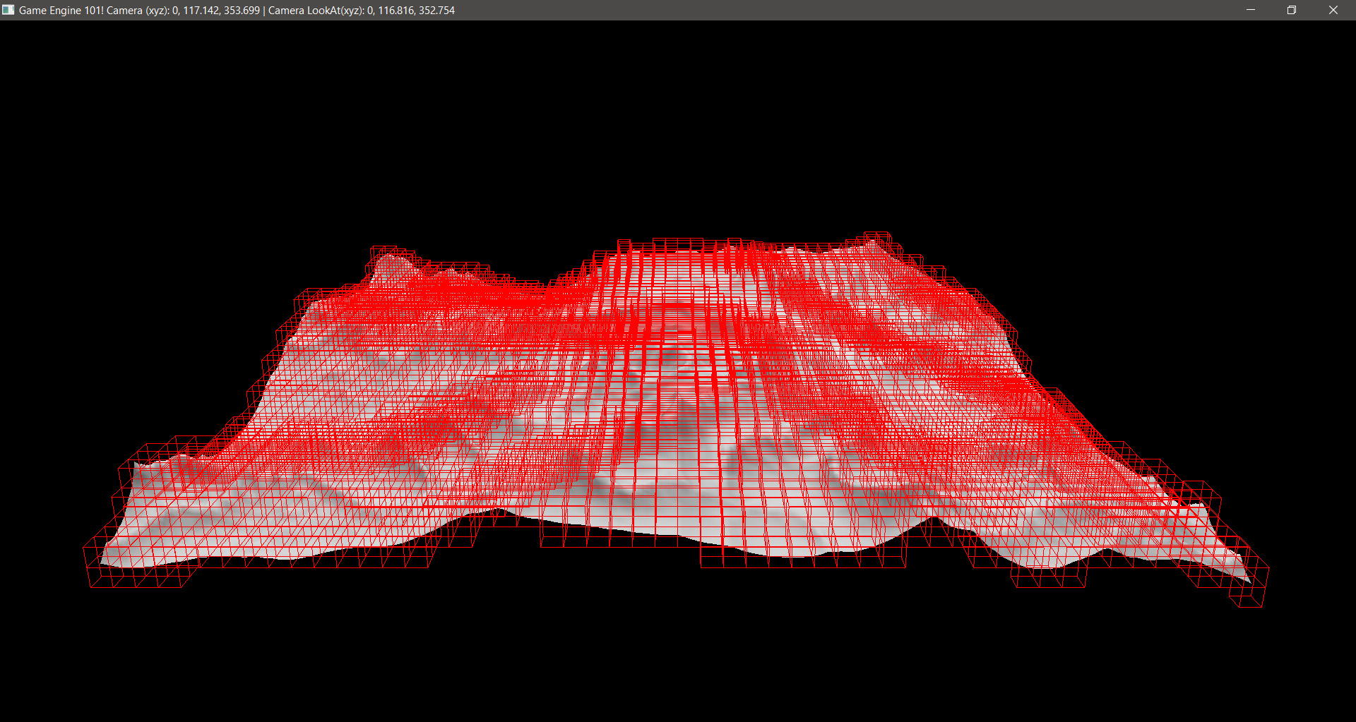
As it can be seen, there was no AABB where it would not have a triangle inside it. So, it was working fine.
Depending on each project, you may find more useful to create nested AABBs. However, for what I had in mind, I found it easier to just create all AABBs at once.
Printing only one AABB where it matters
At first, Feeney’s Class worked great, but now I wanted to print only one AABB where a debug sphere would represent the object to test the collision. In other words, wherever was the sphere and if there was an AABB there, it should print the AABB. The problem was that the way cDebugRenderer worked it would not allow me to print one AABB and then erase it and print another one. Of course I could change his class to do so, but as it was already very complex I decided to build my own to do the job: cSimpleDebugRenderer. I decided to not create a specific shader for it, as the previous class, but to have its own VAO, so I could create a geometry and reuse it whenever I wanted it. The first geometry was obviously a cube.
There was two basic methods: genDebugGeometry() and drawDebugGeometry() that would do the job (parameters omitted).
Nice. I got it working too. Now let’s test for a different sized AABB!
Cool huh? Ok, time for the normals…
Visualizing the normals
Normals are not only important for collision detection, but here they play some key roles. The first one is tell which side of the triangle is facing outwards. The second is to compute the reactions to the collision. Before all that though, we must make sure they they at least are there correctly. If you are calculating the normals by yourself or parsing it from a file, you have to be sure you have them right.
In my case, I was receiving the normals from a file, however I wanted to print them differently. The file was giving me a normal per vertex and I wanted one per triangle, at its centroid. To accomplish that, I first added a vec3 faceNormal to the struct sAABB_Triangle and then, when reading the triangles, I just added each vertex normal and then normilized the result. For the Centroid, another vec3 was created and added to it. Simple math to calculate it while reading the triangle will do the job.
The code is as simple as this:
    float centroidX = (A.x + B.x + C.x) / 3;
    float centroidY = (A.y + B.y + C.y) / 3;
    float centroidZ = (A.z + B.z + C.z) / 3;
Where A, B and C are the vertices of the triangle.
To render the normals, I created a simple unit line, which is a line with length of 1, and then saved its VAO and Buffer IDs to be able to call it at runtime. The line was created facing up (using the Y axis for that). To draw it properly, in the drawDebugGeometry() I passed the Centroid, the color and a matrix with the orientation of the face normal. The function then moves the line to the triangle centroid and rotates it to match the normal orientation. In the code, I did that for each normal that I wanted to show.
The idea was having a vector of triangles for each AABB as described in my AABB post. So for printing, for the AABB that we want to print the normals, we just have to go through each triangles and make the proper calculations. The code looks like this:
for(int i = 0; i < theAABB.AABBsTriangles.size(); i++)
{
    glm::vec3 fn = theAABB.AABBsTriangles[i]->faceNormal;
    glm::vec3 cn = theAABB.AABBsTriangles[i]->Centroid;
    glm::quat qNormal = glm::rotation(glm::vec3(0.0f, 1.0f, 0.0f), fn);
    glm::mat4 matNormal = glm::toMat4(qNormal);
    glm::vec3 normalColor = glm::vec3(0.0f, 0.0f, 1.0f);
    g_simpleDebug->drawDebugGeometry(cn, g_lineID, normalColor, matNormal);
}
The result:
If you have a good eye you can see that some normals are printed outside the AABB. This is expected, as some triangles are not completely inside an AABB.
The triangles
Why bother showing the triangles as we already have a good idea of them through the mesh? Well, to make the test lighter, I decided to not check every triangle in an AABB. That way I could visualize only the triangles that would matter for that physics step. Imagine if you have a complex mesh, or say a terrain with a lot of houses on it. Do you really want to test collisions on triangles that are not facing the collision point?1 In other words, I decided to only test collisions on triangles where its normals were facing the test point. To achieve that, a simple math between the point and the normal with a Dot Product was needed. If the result was positive, it means that the triangle was facing the point and we should include it in the collision test. The code for that (inside the loop of triangles) is:
glm::vec3 pointAtOrigin = point->position - triangle->centroid;
if(glm::dot(point, triangle->faceNormal) < 0.0f)
{
    continue;
}
As the faceNormal value is relative to the origin we have to bring the point to the origin to make our calculations. pointAtOrigin thus will have this vaule. Then I just checked for their dot product as described and if they were negative, that triangle would be skipped.
The results:
For this case, the sphere is coming from under the ground, so you can easily see that the triangles that are not “facing” the sphere are no being printed, thus they will be excluded from the calculation process at the Physics step.
With that, the visual aiding is done and we can pass with confidence to the collision detection per si.
Conclusion
Visualizing what you are trying to implement can play a big role in saving time at the actual implementation of your collision detection system. Also, implementing that visualization is half way through the process of actually implementing the collision that you have in mind, because in most cases you will use the same logic for both. I have found it very fun and it made things easier at later stages.
I hope this has helped you in any way. Please feel free leave a comment or, if you want to contact me, use any means at the bottom of this page.
Have fun coding,
Jorge Amengol.
1. Later implementing the collision, I did find that I needed to test for inverted triangles, because the collision might have happened and the point will be under the triangle already (almost always) and we do have to check for them.