Hi, I’m Jorge Amengol, a fresh graduate student of the Game Development - Advanced Programming course at Fanshawe College, Canada. I started this series of posts to register my own progress throughout the program and also serve as a reference for me on important subjects in the future. Though it is a personal record, you might find the subjects discussed here useful. Feel free to make comments at the end of each post.
Introduction
The course is getting very intense with so many new concepts to grasp. The last couple of Graphics1 classes kind of lost me with all the transformations an object has to suffer to be able to display correctly on screen in a “3D way”. Professor Feeney had said many times that what we see on screen is all a lie and, after a little research, I have found that he is right indeed. Let’s see why.
The Coordinates
The first thing to know about a 3D model is that there are 3 coordinates for each vertex of it. So, for the bunny that we have seen in class lately, each vertex has a X, Y and Z point in space. Until this point we were projecting it as a 2D, not considering its Z coordinate, although they were ther all ther time in the PLY file.
The Model Space
What we just view is what is called the Model Space. I think it only have a name because of the other spaces that we have to handle to show something 3D on screen. The Model Space is the most intuitive one, and its defined by the coordinates of the model itself.
Model Space: all vertices defined relatively to the center of the model.
The World Space
But then we want to have more than one object being rendered, and most of the time, they will be in “different positions”. To do that, we translate the object from its Model Space to another point in World Space. I will not get in details about matrices transformations here, but basically the matrix that do the job of translating the model from the Model to the World space is the Model Matrix.
World Space: all vertices defined relatively to the center of the world
[Model Coordinates] –> Model Matrix –> [World Coordinates]
The Camera Space
The World Space would be almost all we wanted if we had a “fixed camera”. By the way, OpenGL do not have any idea of a “camera”, neither it gives us an “easy to use solution” for it. We have to construct it all by ourselves. This is where things can get a little nasty if we are a “believer” of the Computer Graphics 3D world. In fact, as Mr. Feeney said, it is all a lie and there is no camera. What we do to “move a camera” is to move all the world instead. So, if we want to move the camera up 3 units we move the world down 3 units. So, everything we want to do with the “camera”, we do the inverse with the world. The good news is, if you are using the GLM library or the GLSL itself, you can use the lookAt() function to produce the View Matrix that we want. If you take our Model Matrix and multiply by it, we translate our object from the World Coordinate to the Camera Coordinate.
Camera Space: all vertices defined relatively to the camera
[World Coordinates] –> View Matrix –> [Camera Coordinates]
The “Homogeneous” (Projective) Space
The last transformation in the chain is not for the faint of heart. It has to do with projection and how we would represent a 3D world in a 2D plane (the screen). The math behind it is not very trivial and is related to Projective Planes, a kind of expanded plane concept where two parallel lines, in an Euclidean plane, would meet at infinity.
During the 19th Century, from that Projective Plane, a Mathematician named August Ferdinand Möbius came up with this idea of Homogeneous Coordinates and introduced the notion of any (x, y) point in the 2D space being represent by a triple (x/w, y/w, w). For instance, the point (2, 4, 2) and (4, 8, 4) in Homogeneous Coordinates would be the same (1, 2, 1) or just (1, 2) in Cartesian Coordinates. That simplified the Projective Planes pretty much, and adding another dimension to it, we finally get to the projection of a 3D point into a plane: (x/w, y/w, z/w, w).
The set of points represented by this notion is what being commonly called by Computer Graphics programmers of Homogeneous Space, however, the space is the Projective Space and its coordinates are in Homogeneous Coordinates.
So, our 3D models that are in Camera Space have now to be translated to Projective Space using some projective method.
There are two main kind of projections used in Computer Graphics: Orthogonal and Perspective. For the first one, the object is represented by its relatives distances exactly. In other words, if you have a cube of side 1 unit and project it on screen with an Orthogonal projection you can measure all its sides and it should be of the same size. For the second one, the Perspective projection, the cube sides will vary slightly, depending on the distance of their lines from the Point of View.
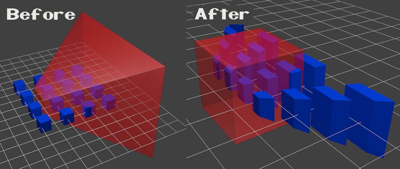
As we all know, this last projection (The Perspective) is the most used in Computer Graphics to simulate the 3D world. Thus, we have to produce a matrix that will translate our object from the Camera Space to our Projective Space, simulating the notion of a perspective into the screen. Basically what that matrix will do is “deform” the object in a way that points closer to the “camera” (with little Z values) will look bigger than the ones further of it (with large Z values).
The effect over the objects should look like this:
 Source OpenGL Tutorial 3: Matrices
Luckily, again if we use GLM, we can produce this matrix with the function glm::perspective(). This last matrix is called the Projection Matrix.
So, the final part of the puzzle is:
Perspective Space: all vertices defined in a small cube. Everything inside the cube is on screen.
[Camera Coordinates] –> Projection Matrix –> [Homogeneous Coordinates]
And putting it all together we have:
[Model Coordinates]
………….|…………..
Model Matrix
………….|…………..
[World Coordinates]
………….|…………..
View Matrix
………….|…………..
[Camera Coordinates]
………….|…………..
Projection Matrix
………….|…………..
[Homogeneous Coordinates]
Conclusion
What I tried here with this post was to connect the dots we saw in class with some math background to make myself a little bit more conscientious of what is happening on screen. The conclusions that I made here are not at all rigorous as mathematicians would expect. They are just an attempt to make the subject more “sensible” to me. Also, I have just a regular Computer Science Math background and most of the conclusions here were in fact built from internet resources and the links are right there at the bottom of this page so you can make your all conclusions too, that may be different from mine.
The lie in Computer Graphics is the same lie we have with any projection. The projection is a representation of something that is not really there. So, what we see on screen, basically a 2D plane, is a representation of a 3D world that can not be seen as is on the screen. However, Graphics Cards nowadays do this representation so often and efficiently that most of time we don’t even see the screen as a simple 2D plane and we willingly believe in that “lie”!
I hope this has helped you in any way. Please feel free to leave a comment or, if you want to contact me, use any means at the bottom of this page.
Have fun coding,
Jorge Amengol.
Sources:
OpenGL Tutorial - Matrices
The Matrix and Quaternions FAQ
Homogeneous space
Homogeneous Coordinates
August Ferdinand Möbius
Projective Plane
Projective geometry and homogeneous coordinates
Projective Geometry